With the new motor installed, the next major task was to install the new battery pack.
The cells chosen were 45x ThunderSky lithium-iron-phosphate at 100 AH per cell. That gives a 145 volt pack at 100 AH or about 14 kilowatt-hours total capacity, or perhaps 9-10 kilowatt-hours usable capacity.
I bought the cells from Lightning Motorcycle, and also worked with them to design a custom battery box and install one of their Battery Management Systems. It’s their considered opinion that cells like the ThunderSky design (rectangular plastic cells) must be contained on all sides to prevent swelling. To that end, their preferred design is a stainless steel box built out of U-shaped channels, with a plastic cover.
We did lots of measurements and going through several design ideas before settling on two custom boxes in the engine compartment, and another box underneath a ledge in the very rear of the passenger compartment. This meant the back seat did not get sacrificed to hold the battery pack, and the top could be lowered in the normal fashion.
The rear seat isn’t terribly useful on the Karmann Ghia so I always used it as a cargo area, instead.

The cells sitting on the garage floor.

The box for the passenger compartment, with a few cells in it. The flange you see is for bolting it to the car, and there’s another dohickey on the side you can’t see to bolt the box to the firewall. Since this box lives in the passenger compartment, it has to be securely bolted to the car so that in case of an accident it doesn’t become a flying missle and kill everyone inside the car.

This is what we did for every cable entrance/exit from one of the boxes - drill a hole and insert a rubber grommet.

Test fitting one of the rear battery boxes, and its plastic cover. The cover gave a little protection against weather, allowed us to show off the battery box design without fear of electrocution, and prevented accidental wrench drops from starting a plasma ball. Look closely and you see the box is bolted to the firewall.

Same box, empty, with no lid.
The studs on the side of the box hold the platform that supports the heat sink and controller.

Fully populated battery box ready to go in, almost. The main battery cables are installed, as are the straps forming the power bus. What’s missing is the BMS wiring harness.

The BMS wiring harness ready to go in. This involves 45 thin wires (?46 wires?), one going to each cell, and are connected back to the BMS unit. They let the BMS measure the voltage of each cell individually, and during charging to connect resistors to the cells to bleed off energy if needed. Each wire has a micro-fuse in it to prevent accidents.

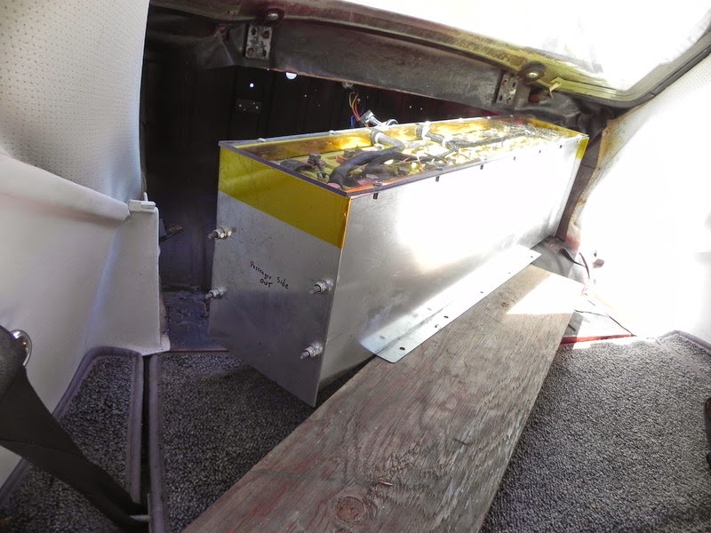
Passenger compartment battery box, with all wiring including BMS installed and ready to go.

Cover installed, even more ready.
The protrusion on the front of the box is the other half of the mounting system. Bolts through the firewall go to this protrusion, bolting it in place.
Installation involved two people working from each side of the car, moving it carefully into place, lining it up with some holes that had been drilled in the firewall. Later there were holes drilled in the floor of the passenger compartment, to bolt it into place at the bottom.
Positioning.

In place, ready to bolt down.

Rear battery boxes mounted in place, ready to be populated. The rear boxes were simpler to deal with because we could easily access the cells. That meant the boxes were put in place empty, bolted down, and then populated afterward.
You see here two cables coming through the firewall. Those go to the battery box mounted in the passenger compartment. The complete battery circuit starts in one of the rear boxes, goes to the box in the passenger compartment, then back out to the other box. That means the positive-most pole of the pack is in one rear box, and the negative-most pole is in the other rear box.

Cells ready to be installed.

Half of the cells, installed. The sheet of paper is the map of the battery pack and BMS wiring harness.

Both halves of the pack installed, the BMS box in place, the POTBOX in place. The sheath-covered wires are the BMS harness. As said above each contains the individual wires going to the cells, and they end at connectors which plug into the BMS box. Inside the BMS box are the balancing boards (4) and the master board that drives the BMS.
The BMS is Lightning’s design, and is used on their race bikes.